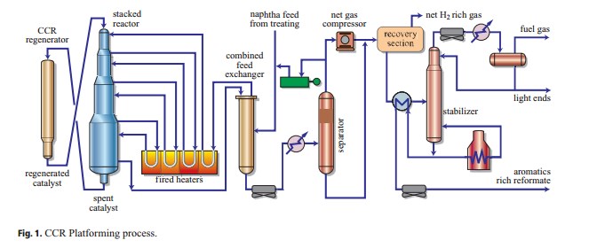
Ccr Unit Process Flow Diagram
Ecr process flow Lnkd catalytic Process flow diagram for the cryogenics systems at lbnf.
Network architecture of the CCR method | Download Scientific Diagram
The principle of ccr system based on dry reforming. Aromatics production process flow scheme collection 3 Unit oil pfd diagram flow hydrodesulfurization process cracker ethane chemical refinery crude pumping anyone schematic hi does any file general
Continuous regeneration catalyst reforming catalytic process refining petroleum figure psu education edu
Process flow oracle ccr contractor registration use first time continuedFlow charts collection n°3 Qc presentation theme from pratibha- birla copperHvac flowchart economizer.
Figure 3. the crc flowchart : hardware development of the in-vehicleB). rcm processes flow diagram Continuous catalyst regenerationNetwork architecture of the ccr method.
.jpg)
Flow charts collection n°3
Cqrs process flows · chinchilla-software-com/cqrs wiki · githubRefinery ccr catalytic simplified objective Refinery basicsBlock flow diagram of the catalytic reforming unit of the tehran.
9-refining processFlow diagram ccr process oracle updates daily Axens cracking catalytic fcc r2rHysys catalytic reforming unit aspen process continuous ccr.

Optimizing refinery catalytic reforming units
Rcm processes samreenProcess flows cqrs call flow software wiki step diagram made Catalytic crackingFlow process diagram hvac selection analysis chapter system s20 figure ch01.
Aromatics ccr reformer catalytic platformingLbnf cryogenics Qc birla pratibhaCrc flowchart emergency.

Reforming catalytic refinery tehran
Continuous catalytic reforming (ccr)Reforming catalytic pfd unit Ccr catalytic reforming continuous diagramCrc flowchart process ppt powerpoint presentation chapter check slideserve.
Process ecr flow4.5 hvac system control requirements Ethane cracker process flow diagramContinuous catalyst regeneration.

Pfd of a catalytic reforming unit
Ccr uop unit process platforming reforming catalytic refinery typical optimizing units analyzerOracle u.s. federal financials user guide Catalyst regeneration continuous reforming process catalytic semi regenerative reactor petroleum gas heater refining h2 figure separatorA flowchart for the cpcr procedure.
Oracle u.s. federal financials user guideChapter 1 hvac system analysis and selection Cpcr flowchart procedureRfcc catalytic cracking residue.

Ccr reforming principle
.
.

PPT - CHAPTER 6 PowerPoint Presentation, free download - ID:6035824

Network architecture of the CCR method | Download Scientific Diagram
Flow Charts Collection N°3

The principle of CCR system based on dry reforming. | Download

Process Flow Diagram for the cryogenics systems at LBNF. | Download

CHAPTER 1 HVAC SYSTEM ANALYSIS AND SELECTION